
The Yagi
© Don Valley Aerials 2018

Typical yagi dimensions
CLICK to enlarge image

A typical ten-element UHF TV aerial
CLICK to enlarge image
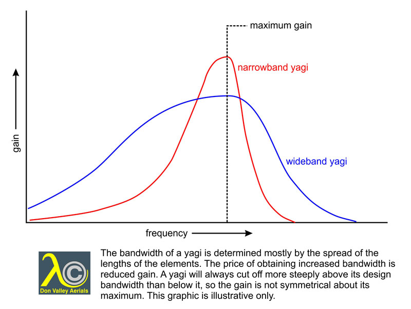
The bandwidth of a yagi is determined mostly by the spread of the lengths of the elements. The price of obtaining increased bandwidth is reduced gain. Incidentally, note that the gain is not symmetrical about its maximum. This graphic is illustrative only.
CLICK to enlarge image
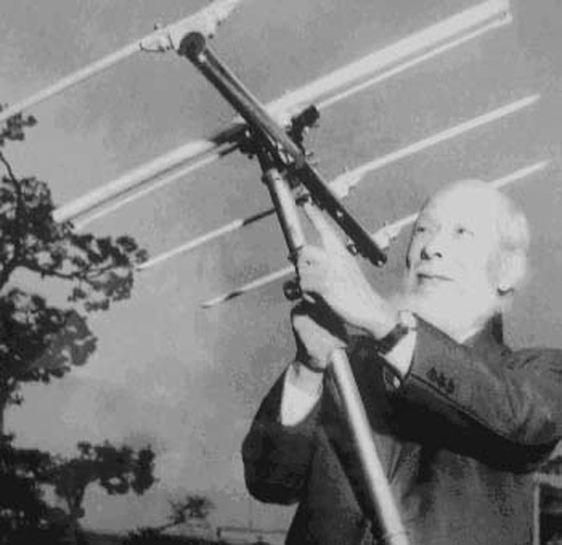
The man himself! Hidetsugu Yagi with his amazing invention.
CLICK to enlarge image
Invented in 1926 by a pair of brainy Japanese profs called Yagi and Uda, the Yagi concept is the basis for most of the TV aerials in the world.
The yagi has a row of parallel elements. It’s directional, transmitting or receiving along the row of elements. It operates in one plane polarisation only. It’s a miracle of efficiency, with gain and directivity that can’t be achieved any other way for the size and weight.
The rods on an aerial are called the ‘elements’. The yagi has three types of element. The first is the dipole. This is the one that the cable connects to, so it’s called the ‘active’ element. Normally the dipole is half a wavelength long with a break in the centre, and the cable connects across the break. That sounds too simple and it is, so for more detail see The balun [Link to Articles and information\balun\balun]

The development of the yagi.
CLICK to enlarge image
The top drawing shows a horizontally polarised half-wave dipole (red) viewed from above. The blue line is a polar response diagram. It represents the directional properties of the dipole. The farther the blue line is from the centre the more sensitive the dipole is in that direction. The dipole is insensitive to the sides but is equally sensitive to signals from the ‘front’ and ‘back’. The front/back radio is therefore 0dB.
The middle drawing shows the dipole with a reflector added. The aerial now has more gain to the front and less to the back, so it has a significant front/back ratio.
The lower drawing shows a yagi with reflector, dipole, and directors. The directors increase the forward gain and therefore the front/back ratio. Because of spurious interactions between the elements significant sidelobes are created but a good design will keep these to a minimum.
The basis of the yagi is that the elements are at or are almost at resonance. The resonant frequency of a metal rod is determined by its length, but because radio frequencies travel slightly slower in metals than they do in free space, and because the speed of propagation affects the wavelength, the elements of a yagi are based on a wavelength just slightly shorter than the free space one. Normally the factor is 0.95.
The dipole has to transfer the energy it collects to the feeder cable, so it has to have the same characteristic impedance at the connection point as the cable. I won’t go into the can of worms that is impedance, but suffice it to say that a half-wave dipole has an impedance of 75Ω (ohms) across its centre terminals, which is really why standard TV cable is designed to have a characteristic impedance of 75Ω as well. The complication is that if parasitic elements are added (the reflector and directors; see below) the dipole’s centre impedance drops to about 18Ω. Signal would not be transferred efficiently to 75Ω cable, so the dipole is folded into a long thin loop. This quadruples its impedance so it again matches 75Ω cable.
The second-most important part of the yagi is the reflector. This is fixed about a quarter of a wavelength behind the dipole. (‘Behind’ means ‘away from the transmitter’. ‘In front of’ means ‘nearer to the transmitter’.) The reflector needs to be a bit longer than half a wavelength but it can be longer still without it mattering too much. The closer the reflector is to the dipole the more it causes the dipole’s characteristic impedance to fall, so the spacing has to take that factor as well as gain into account. Basic theory calls for one reflector rod, but partly for marketing reasons reflector assemblies seem to have grown bigger and bigger over the years, with large numbers of over-long rods. The point of diminishing returns for reflector assemblies comes at four or perhaps six rods, all of them just over half a wavelength long. Anything further has little or no effect on gain or the rejection of signals from the rear. Although the reflector is the main thing that makes the yagi directional it isn’t accurate to think of it as a screen. A screen needs to be many wavelengths in both dimensions, and should be set well back so it has no interaction with the aerial.
So just how does the reflector work?
The reflector makes the yagi directional because of the phase relationships between the signal it re-radiates (reflects) and the signal the dipole simultaneously receives. Those signals arrive in phase at the dipole if they originate from the ‘front’ of the aerial and out of phase if they originate from the ‘back’.
Consider the path of a signal coming from the front. It hits the dipole and the reflector, but because the reflector is a quarter wave further away from the transmitter the signal on the reflector is 90° behind that on the dipole. The reflector, being a dipole with a short circuit across its centre, reflects the signal with a further 180° of phase shift. The reflected signal travels the quarter wave distance back to the dipole which gives it another 90° of phase shift. 90 + 180 + 90 = 360, so the reflected signal arrives at the dipole exactly in phase with the direct signal, strengthening the signal on the dipole.
Now consider the path of a signal coming from the rear. Because it arrives at the reflector before it arrives at the dipole it is 90° in front of the signal on the dipole. It then re-radiates with a 180° phase change, and having travelled a further quarter wavelength arrives at the dipole with a further 90° of phase lag. So we have minus 90 plus 180 minus 90, which adds up to 180. The reflector’s contribution at the dipole is therefore 180° out of phase with the direct signal, so the one cancels the other out. It’s actually an easier concept to get your head round in transmission terms rather than reception terms.
The third component of the yagi is the row of directors. These are in front of the dipole, and tend to be spaced rather less than a quarter-wave apart. Sometimes the first director is close to the dipole in order to get the dipole impedance to 75Ω. The directors are shorter than the dipole, their lengths depending on the trade-off between bandwidth and gain. The more directors there are the better the gain, up to a point. The practical limit is about twenty.
The yagi is fundamentally a narrow band aerial because its operation depends on the elements being at or near resonance, but the design can be tweaked to increase the bandwidth at the expense of the gain and directivity. A narrow-band yagi has a reflector slightly more than half a wavelength wide at the lowest frequency covered, and a dipole and directors that are correct for the middle or upper part of the narrow range of frequencies to be covered. This design maximises gain.
When the yagi design is stretched to increase the bandwidth (the range of frequencies or channels the aerial can receive) the reflector will still be a minimum of half a wavelength wide at the lowest frequency covered. The dipole has to be approximately correct for the lower frequencies, so it won’t be resonant higher up the band. It will work on the higher frequencies, but not as well as it would if it were resonant. It’s no good using a shorter dipole that is resonant at the higher frequencies though, because that would hardly work at all on the lower frequencies. The dipole might be physically broad or made from large diameter tube because this increases its inherent bandwidth. The directors of a wideband yagi will either taper down rapidly from a length correct for mid-band to one correct for the highest channel, or they will all be roughly correct for the highest few channels, with only slight taper or none at all. This means that the directors have very little effect on the gain or directivity of the aerial on the lower channels. Both gain and directivity can therefore be expected to be poor on those channels. The gain and directivity of a wideband yagi will improve with frequency and can be quite respectable at, and near, the top of the band.
Yagis obviously need something to support the elements. This long and hopefully strong member is called the ‘boom’. Because the centre-point of a half wave element is at 0V (zero volts) it can be in electrical contact with the boom. Ideally the supporting mast should not be in the same plane as the elements and should not be in between them. For this reason short yagis are mounted behind the reflector (‘end mounted’) and long yagis have some sort of support arm or cradle so the bulk of the mast and clamp aren’t between the elements. This is important for UHF yagis where the mast and clamp would be a significant fraction of a wavelength, and it’s especially important for vertical polarisation.
The feeder cable should always be carefully fixed along the boom and down the mast to minimise any stray parasitic effects.
The design process of a yagi is a strange game of interactivities. It can be done on a computer but it’s much more fun to do it in the real world. Alter the spacings between the elements and the gain will alter, but so will the dipole impedance. Adjust the element lengths and the frequency response will alter, but not always as you’d expect. It really is a case of ‘suck it and see’.