
The log periodic

A typical horizontally polarised UHF log periodic.
A typical horizontally polarised UHF log periodic
Log periodic aerials have two parallel booms, usually close together. These booms together form a transmission line. A series of half wave dipoles are attached to the booms, each dipole having one quarter wave section fixed to Boom A and the other to Boom B. Each dipole (except two or three; see later) are tuned to a frequency within the range required for reception or transmission, and are fixed in order of resonant frequency along the two booms. Each dipole is connected in opposite phase to its neighbours. The two booms are connected together electrically at the low frequency end of the aerial. The feeder cable is connected across the two booms at the high frequency end. The feeder often runs inside one of the booms to its low frequency end, where the aerial is fixed to the mast. Running the feeder inside the boom that is connected to the feeder’s screen seems to reduce the need for balance/unbalance conversion. The dimensions and spacing of the two booms is designed to produce an impedance of approximately 75Ω. For these reasons log periodics don’t seem to need a balun.
 The basic arrangement of a log periodic dipole array
And the extra two or three dipoles? One is just slightly longer than would be resonant at the lowest operating frequency and then there’s another one or two that are shorter than would be resonant at the highest operating frequency.
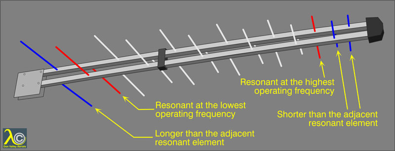 The longest and shortest dipoles are resonant just outside the design bandwidth.
Each element of a log periodic is longer or shorter than its neighbour by a fixed ratio, and the inter-element spacing also increases or decreases by a fixed ratio. The inter-element spacing is generally a quarter wavelength of the adjacent dipole’s resonant frequency, or a bit less.
The smaller the ratio of the lengths of adjacent dipoles the higher the gain. A large ratio will lower the gain but increase the bandwidth for a given number of dipoles. Just as the yagi is inherently narrowband the log is inherently wideband. Almost all logs sold in the UK for UHF TV reception are wideband in that they cover all the channels used for TV broadcasting. However Vision Products have a ten-dipole product that covers Channel Group A only. The gain as you might expect is slightly better than that of a ten-dipole log designed for all channels.
 The smaller the ratio of the lengths of adjacent dipoles the higher the gain. The upper aerial will have relatively high gain but reduced bandwidth. The lower one will have less gain but more bandwidth.
For a given frequency only a small zone along the boom of the log periodic is active. The zone is centred on the dipoles that are at or near resonance at that frequency. Consider two adjacent dipoles, somewhere about half way along the boom. The incoming signal is in the middle of the frequency range of the aerial, so the two dipoles are approximately resonant and are therefore in the active zone. Feeder reversal and the distance between the two elements gives a phase shift of 360° between them. In other words, for a signal coming from the ‘front’ of the aerial (only) the signal on the two dipoles is additive if it is collected from the front of the boom-cum-transmission line. This is why log periodics are directional, and why the feed-point is at the sharp end. It’s possible for three or even four dipoles to work together in this way. A smaller ratio between the lengths of adjacent dipoles means more dipoles are near resonance for a particular frequency, which is why the gain is higher for such an aerial. There are two things that prevent the dipoles that are shorter and longer than the resonant ones from playing much of a part in reception. One is that they aren’t resonant and the other is that the spacing between them does not produce the 360° of phase shift that is essential for the aerial to have gain and directivity. The spacing between the directors on a yagi can be varied widely (and often is to help feeder matching) but with a log periodic the spacing has to be much more closely defined, and has to take into account the velocity factor of the twin booms. (Velocity factor is the speed of radio transmission in anything other than free space; for instance feeder cable or aerial elements.)
If only a few dipoles are active, why does a typical log periodic have as many as twenty? It’s because the more dipoles there are (for a given ratio between the lengths of adjacent dipoles) the greater the range of frequencies the aerial will receive. This is simply because the range of the lengths of the dipoles is greater.
The active zone shifts with frequency, and you can easily find the active zone of a log periodic for a given frequency. Monitor the signal output of an aerial at that frequency using a meter or spectrum analyser and get hold of one end of each dipole in turn. This will de-tune that dipole. When the signal level drops you’re holding one of the active dipoles.
 The active zone shifts with frequency.
If a log periodic is compared with a yagi of the same size it’s very much a case of horses for courses. The yagi will have much better gain if it’s a grouped one, but if it’s wideband its gain at the lower end of the band might be no better or even a bit worse than that of the log periodic. The main advantages of the log periodic are that the response is very flat right across the band and that the directional characteristics are also maintained at all frequencies. This is where the wideband yagi falls down.
The log will have a far better front-to-back ratio than the equivalent yagi. This means that it is better at rejecting signals from the rear. However the front lobe (the ‘acceptance angle’) of a log is much wider than that of a grouped yagi, or of a wideband yagi when used on the higher channels. This means that if it’s necessary to receive from two transmission sites that aren’t co-sited but are within fifteen or twenty degrees of each other the log can work well.
When it comes to rejecting unwanted signals from the side there isn’t much in it when the polarisation is horizontal, but when it’s vertical the log wins hands down.
Log periodics aren’t just used for UHF TV. Some DAB aerials are logs, and logs are widely used for VHF TV, HF (short wave), and for direction finding.

Band III (170 to 230MHz) is still used for TV in a few countries. The band is too wide to be covered efficiently by a yagi so if several BIII channels are in use log periodics are a common choice. Here we see two Antiference BIII logs.
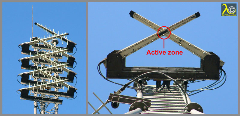
On the left we have a typical TV relay transmission aerial built from log periodics. It looks like a disorganised jumble but it isn’t as you can see in the right hand picture, where we’re looking straight up from the bottom of the tower. The area where the two stacks of logs crosses is the active zone. You can see that this is a Group B relay. Relays have to achieve quite a complicated radiation pattern, putting power into directions where it’s needed and minimising any unnecessary radiation. Because the two stacks of logs are positioned so that they have their active areas exactly in one vertical line, the radiation from the two stacks is in phase as received from all directions. That means that the radiation pattern can be the simple sum of the patterns of each of the two stacks. In that way it’s possible to achieve a polar diagram tailored exactly to the required coverage area. However, if the three transmitted muxes are not on close channels their active zones won’t coincide, so the whole idea falls apart. Ho hum…