
Miscellany of our work
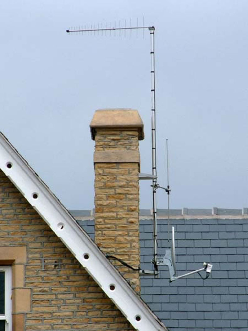
The building was an old health authority outpost that had been converted into flats. The dish and aerials are fairly standard really. The UHF aerial is a vertically polarised log periodic because it needed to be wideband. The vertical dipole is angled so that the null caused by the mast doesn’t attenuate any FM signals that anyone might need.
CLICK to enlarge image
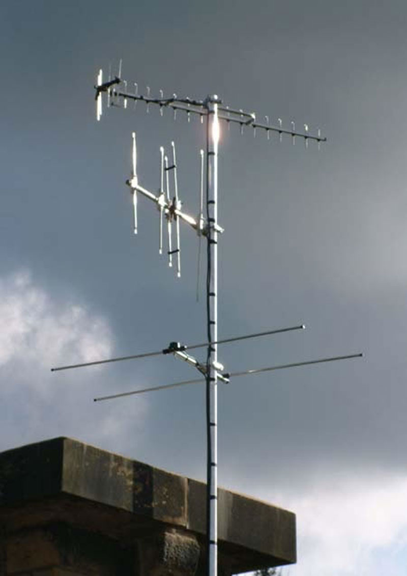
These are the aerials for a distribution system for thirty upmarket flats (whoops sorry, ‘apartments’) in a converted pumping station. UHF was from the local low-powered relay transmitter. There were great inequalities of signal levels between the three multiplexes for no apparent reason. Each mux was level across its bandwidth so we suspected a transmission issue rather than propagation anomalies. It isn’t unusual for the small relays to be like that. No mux was weak enough to cause problems though, so channel filters fixed the uneven levels. DAB and FM reception were only just possible because the valley is officially ‘unserved’, with no reception possible on a car radio, for instance. DAB and FM were therefore a worthwhile addition to the system because it was the only way the residents were going to get any radio reception, other than using Freeview or satellite.
CLICK to enlarge image
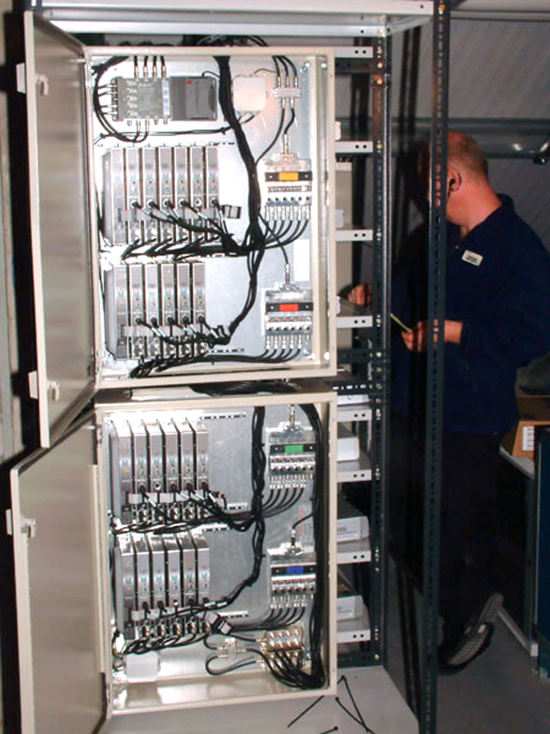
This dates from before digital switchover. It’s part of a head end that provided five off-air analogue channels, six off-air DTT muxes, and 21 in-house channels. The items you see here are the 21 VSB modulators and the channel filter levellers that handle their outputs. Filters were used rather than the manufacturer’s recommended method of using ‘U’ links because the large number of channels and general standard of the installation needed the modulators’ (already very slight) out-of-channel noise to be eliminated as far as possible.
CLICK to enlarge image
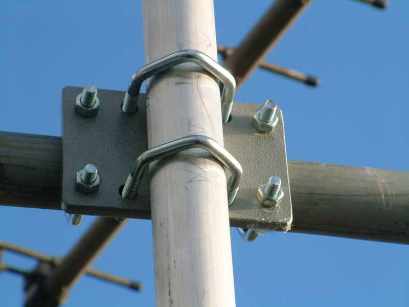
A heavy-duty right-angle clamp
CLICK to enlarge image
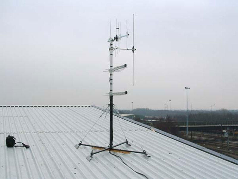
This was an odd one. It was a new building and any sort of wall-mounted installation was forbidden. Our first thought was to make hole in the roof, poke a mast through it, and fit a waterproof ‘boot’, but that turned out to be forbidden as well. In the end we were allowed to fit this strange stand. We had it made by a local engineering firm then we had it powder coated. It was fixed to the roof with a large number of pop rivets, and rested on rubber pads. The little guy wires were a good idea because we could adjust them to allow for the slope of the roof.
CLICK to enlarge image
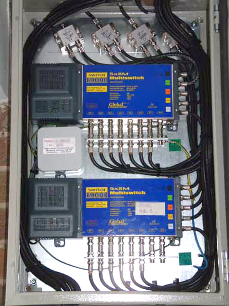
This is the satellite section of a small head end serving thirteen flats
CLICK to enlarge image
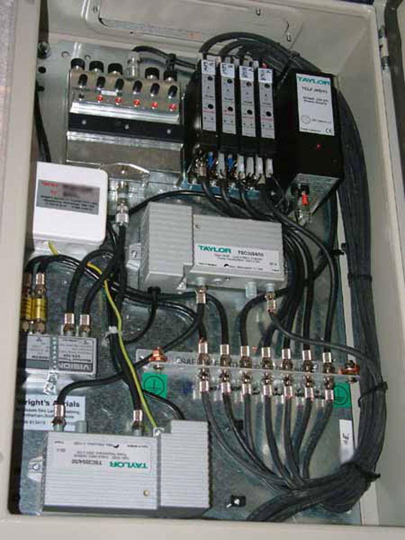
This head end provides VHF DAB radio, VHF FM radio, UHF TV and satellite IF for a row of apartment blocks. There was no possibility of fixing aerials and dishes on these blocks (such was their ultra-modern design), so all signals had to come from this one head-end, carried on rather long underground cables. Repeater amplifiers were installed in some of the other buildings.
CLICK to enlarge image
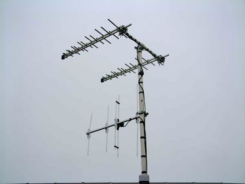
In the days when the UK had both analogue and digital terrestrial TV the available channels were grossly overcrowded so many allocations were unsatisfactory. A prime example was the situation with Emley Moor and Sutton Coldfield. The coverage areas overlap but the channels used by one for analogue were used by the other for digital, and vice versa. There was a large ‘mush area’ which amounted to a serious reduction in the service area of both transmitters.
This aerial was installed in 2007, in the English north midlands. We tried Emley Moor, but Sutton Coldfield caused intolerable co-channel interference. We tried Sutton Coldfield but Emley Moor caused intolerable co-channel interference. We tried Waltham and got nowt because there was a big hill in the way. We went away and did the sums and returned with this array of two log periodics. The inter-aerial spacing was calculated so that the array would reject signals from the relevant angle. This was optimised for the middle of Group B. The array provided reliable Sutton Coldfield reception, which was quite a good result really because when we first erected an aerial the results were pretty dismal.
The new channel allocations for multiplexes 7 and 8 have all the main transmitters using the same channels. This will cause co-channel interference over large areas of the country. The reduction in the bandwidth allowed for broadcast terrestrial TV in the UK (so that the bandwidth can be sold off to the phone companies) is going to exacerbate these problems in the coming years.
CLICK to enlarge image
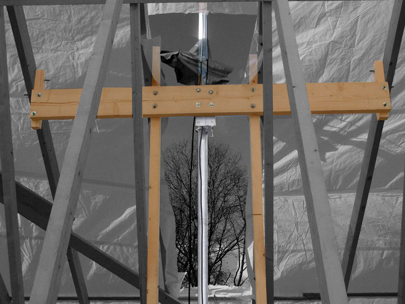
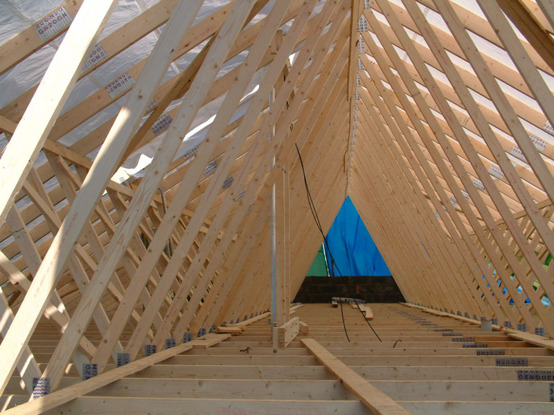
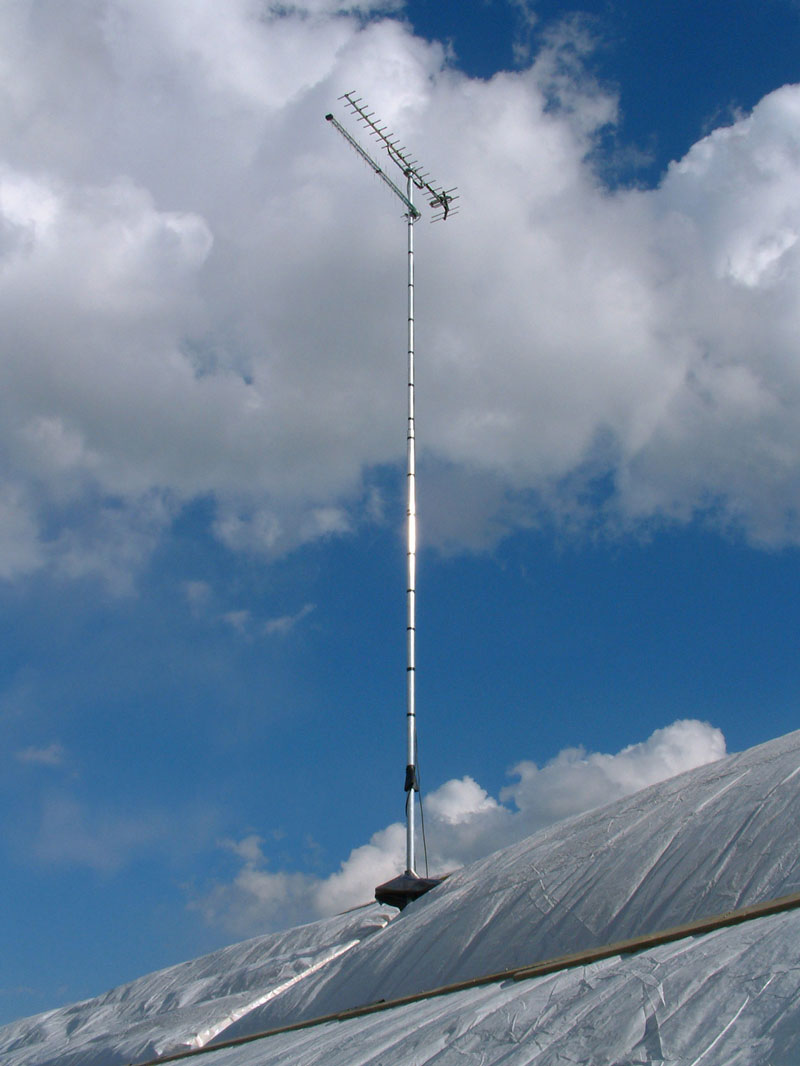
This was an old building that had had a flat roof. The residents clubbed together and had a proper pitched roof built, so we had to do something about the aerial. The only possibility was to have the mast protruding through the new roof, and this picture shows the woodwork we added to support the upper of the two brackets. The lower bracket was supported in much the same way. You can just see the mast as well, which was a 20ft aluminium scaffold tube. The aerial ended up much higher than it had been before, which was really useful because it improved the signal substantially.
There are two aerials because we decided to use both the local relay and the main station, and as it happened they were both in the same direction.
CLICK to enlarge image
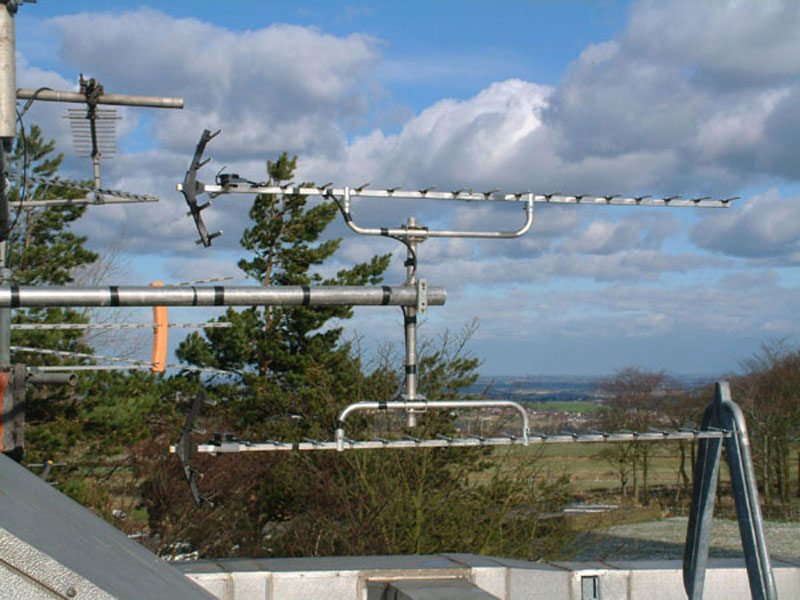
The requirement was to receive a weak signal from a distant transmitter. The site was in the shadow of a high powered transmitter that used the two channels adjacent to the one we needed to receive. To minimise the signals raining down from up above and thus make life a little easier for the filters and amplifiers, two Group B aerials were mounted one above the other and the outputs combined. The distance between the aerials was adjusted for maximum cancellation of the local signals. It worked!
CLICK to enlarge image
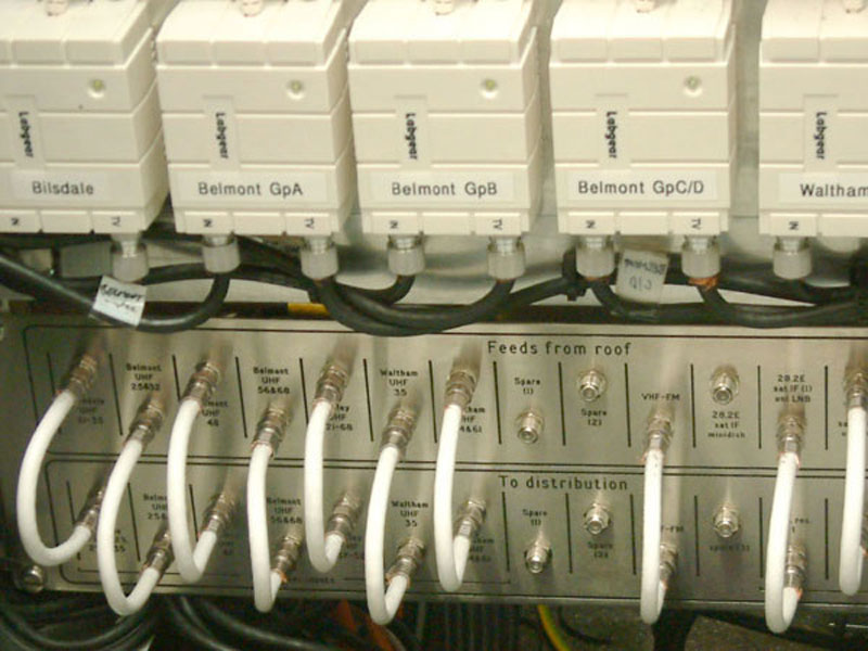
We needed some means of quickly testing the output from each aerial before it was combined with the others. This simple patch panel did the job.
CLICK to enlarge image
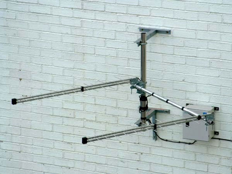
Very strong co-channel signals made rooftop reception impossible. This array uses the building as a screen, and has two log periodics with the inter-aerial spacing optimised for rejection from the direction of the main interferer. The enclosure holds filters and a pre-amp.
CLICK to enlarge image
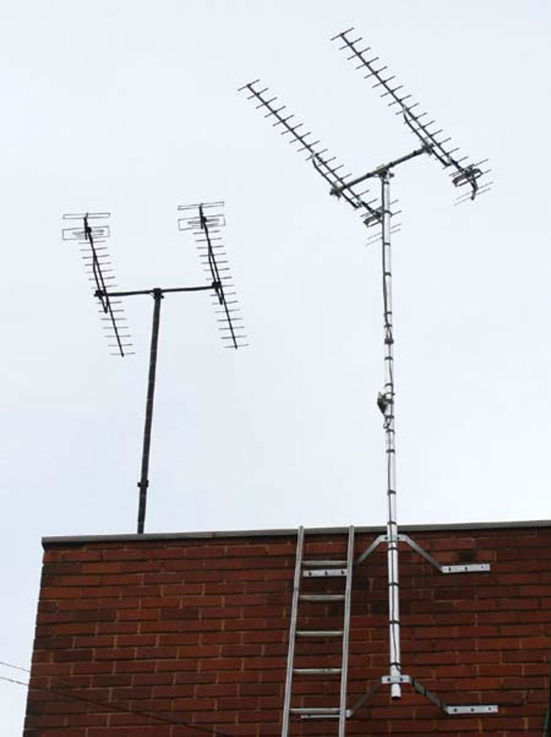
These aerials supply signals to a complex of about 80 flats. The stacked pair on the left comprises two vintage J Beam 18 element Group A aerials. They were installed by us in the late 1970s and nowadays provide useable digital signals in a very poor reception area.
Because of occasional co-channel interference affecting the Group A reception we needed a back up. The pair of aerials on the right receive a weak but generally usable signal from a Group B transmitter. Both sets of signals are carried on the distribution system. Residents have leaflets explaining that duplicate channels will appear somewhere in the EPG (electronic programme guide) and should be used when necessary. Because of channel clashes some multiplexes are unavoidably excluded, but all the main PSB services are available from both transmitters.
CLICK to enlarge image
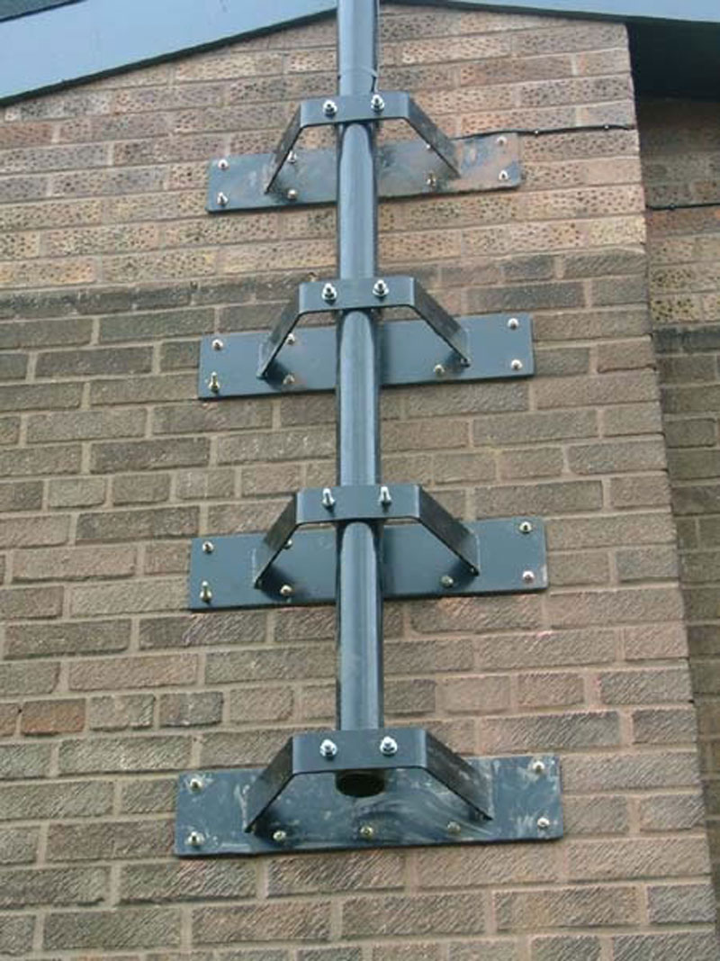
The aerial had to be at least 9m above roof height. There was no possibility of guy wires, and the only fixing location was on this wall. The wall was pretty strong, luckily, because it had a fat internal pillar. We had these brackets specially made, together with the lower mast section. The higher mast section was a 20ft scaffold tube, sleeved into the one you see here.
CLICK to enlarge image
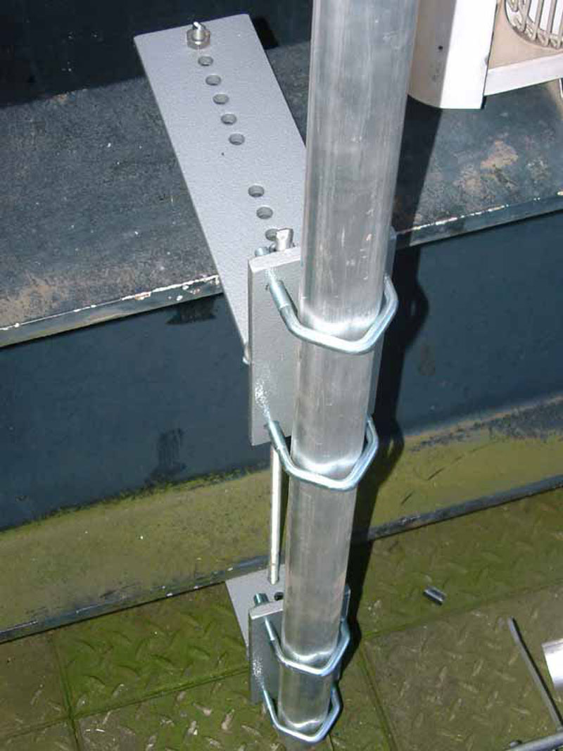
Customised bracketry holding one leg of a gantry onto a large ‘I’ section.
CLICK to enlarge image
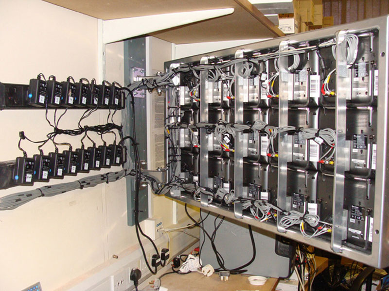
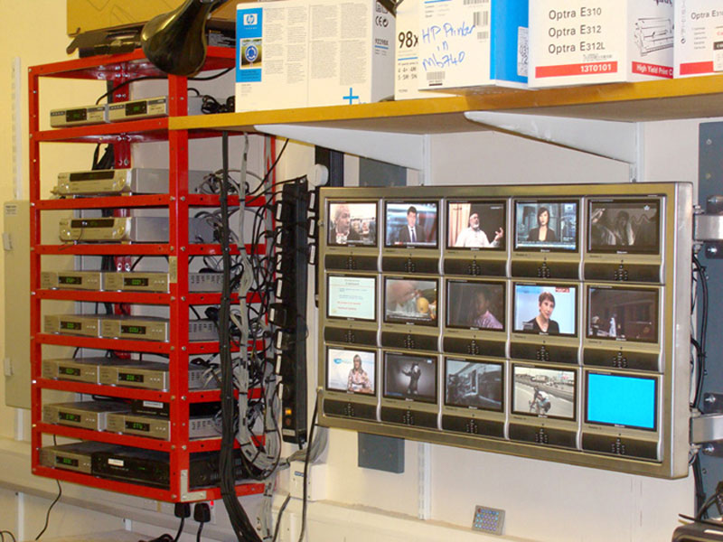
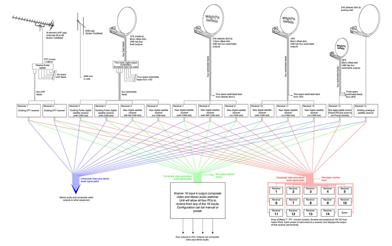
The customer needed to record and distribute manually selected outputs from 14 assorted satellite and DTT receivers. Because the equipment was to be used by different people at different times it was felt that operation should be as foolproof as possible, so we decided to have a separate monitor hardwired to each of the receivers. The upmarket solutions we investigated were well beyond the customer’s budget, so we designed a wall unit which held 15 small domestic TV sets. The unit was wall mounted and hinged so it could be swung forward for rear access. The receivers were supplied with 12V power supply units, and rather than replace them with one large PSU these were used, to reduce cost and the chance of a major breakdown.
A Kramer matrix switcher was used to interface the bank of receivers with the recording PCs, and each receiver also provided an auxiliary output for patch-cord connection to the existing distribution system.
CLICK to enlarge image
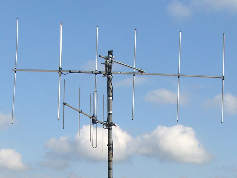
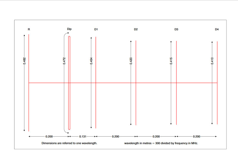
It sometimes happens that radio broadcasters need the best possible reception of a distant FM signal, probably a sister station or one of their own far-flung relays. On a couple of occasions we’ve been unable to get acceptable results with a standard 87–108MHz aerial, so we’ve resorted to making a narrowband aerial from scratch.
The gain and directivity of a standard FM aerial is compromised to some extent by the bandwidth, and an aerial tuned to a specific frequency has a considerable advantage. It isn’t actually that difficult to make an aerial this way. We start with standard dimensions and then ‘proceed empirically’. This is a fancy way of saying that we tinker with the dimensions whilst watching the signal meter. We normally make a basic six-element yagi with a folded dipole. For anyone wanting to have a go at this, the dimensions that seem to work for us are in the second image.
CLICK to enlarge image
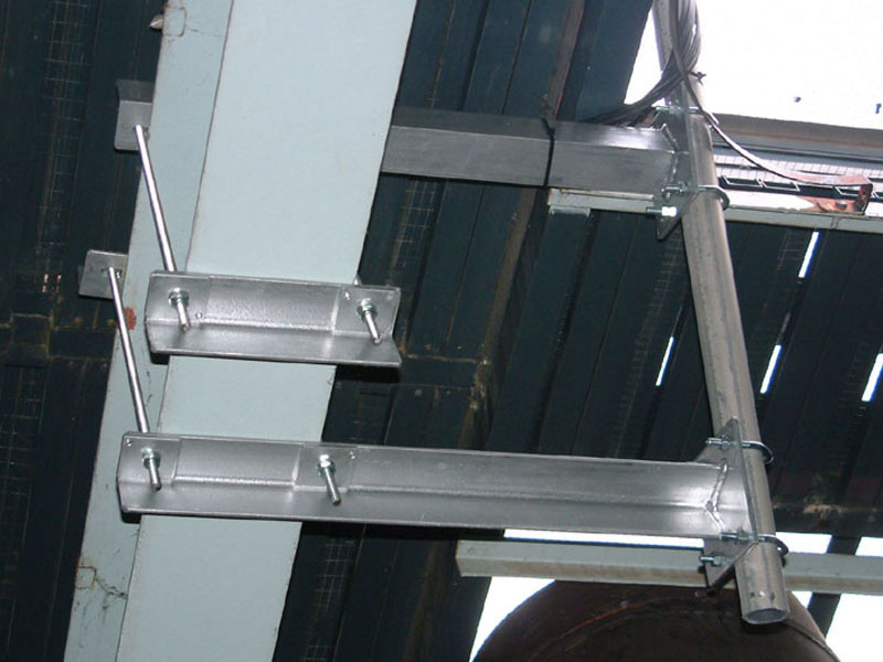
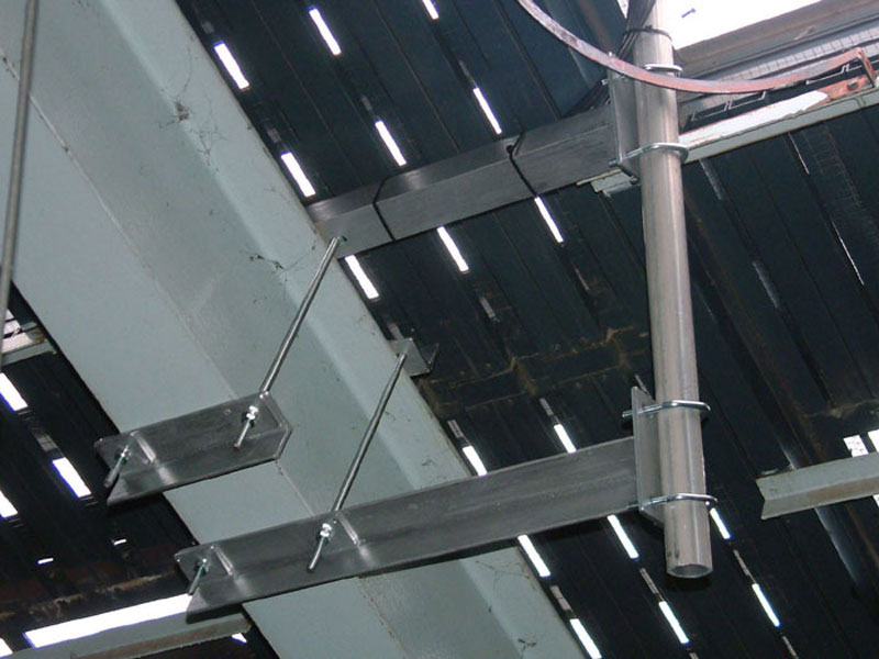
Specially made bracket set to support a dish.
The support had to be very strong and rigid. This solution was considerably more trouble than simply concocting something from Dexion or whatever, but structurally far superior and also much more elegant! I do like something that looks the business.
CLICK to enlarge image
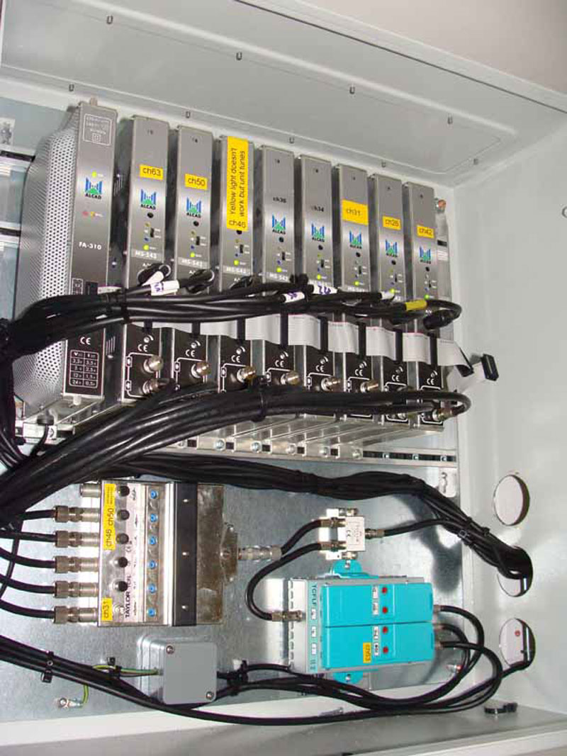
Vestigial sideband modulators and channel pass filters.
CLICK to enlarge image

Modulators, filters, and amplifiers.
CLICK to enlarge image
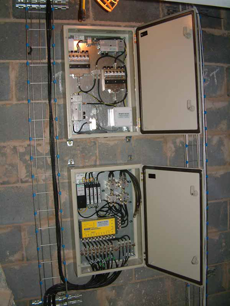
A head-end in the course of installation
CLICK to enlarge image

Fitting a media plate.
CLICK to enlarge image
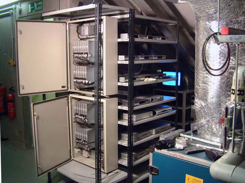
Receivers and modulators.
CLICK to enlarge image
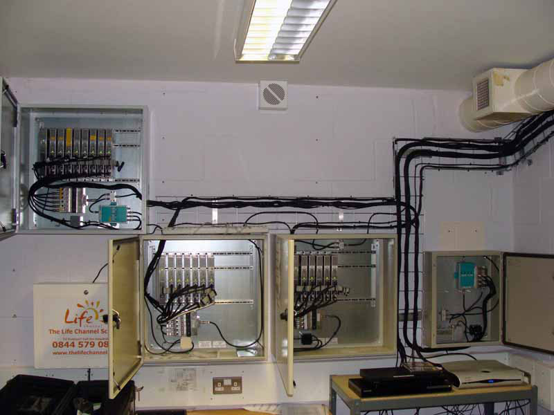
Part of a large installation.
CLICK to enlarge image
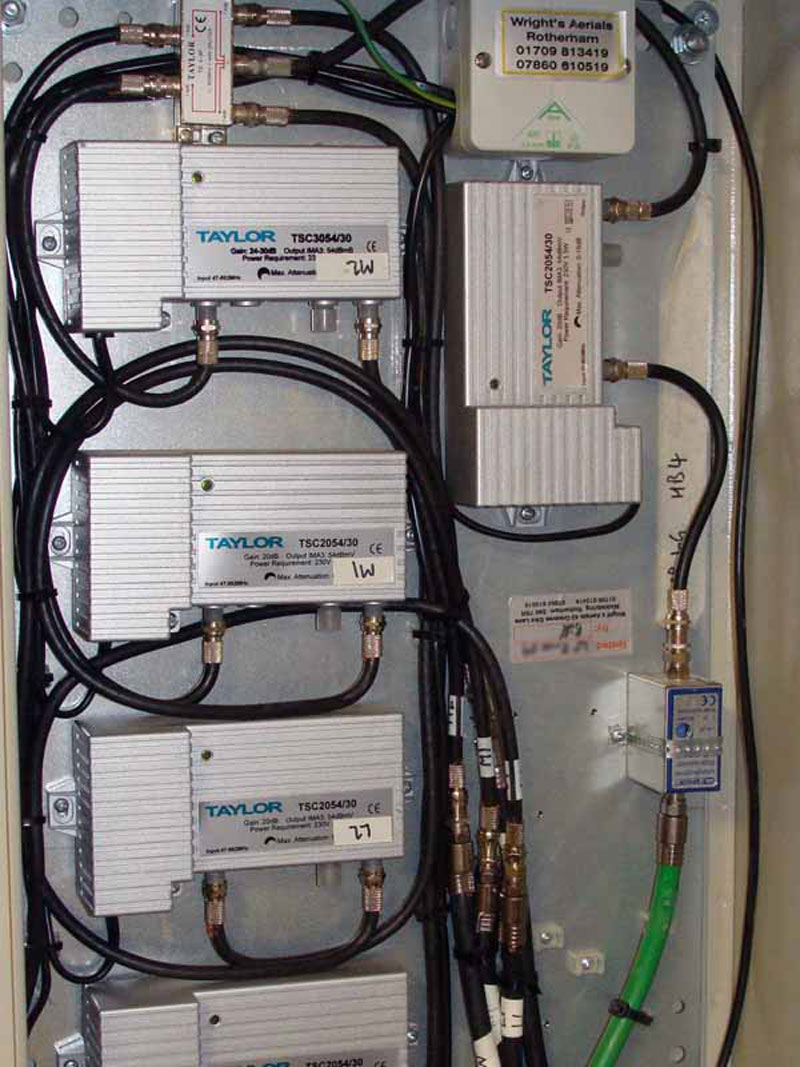
A UHF repeater station.
CLICK to enlarge image
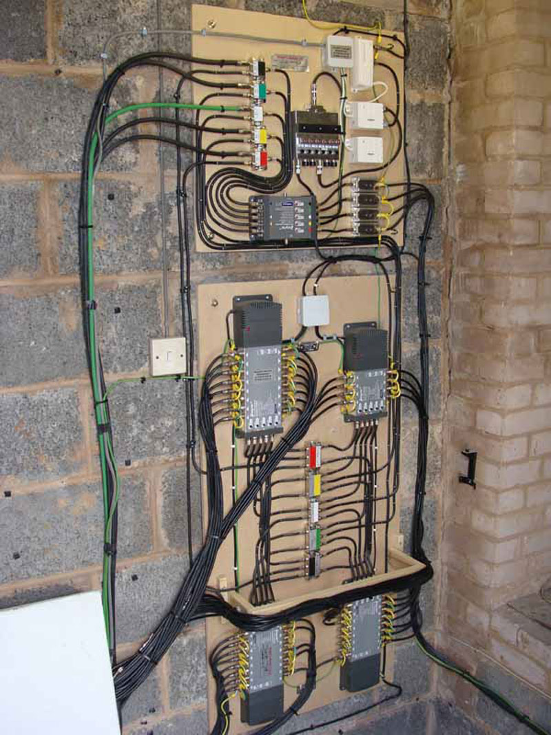
A board-mounted head-end
CLICK to enlarge image
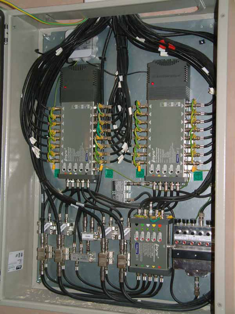
Part of a head-end showing the multiswitches and satellite amplification.
CLICK to enlarge image
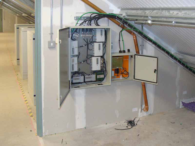
A repeater station, and on the right the power supply for a line-powered line amplifier.
CLICK to enlarge image
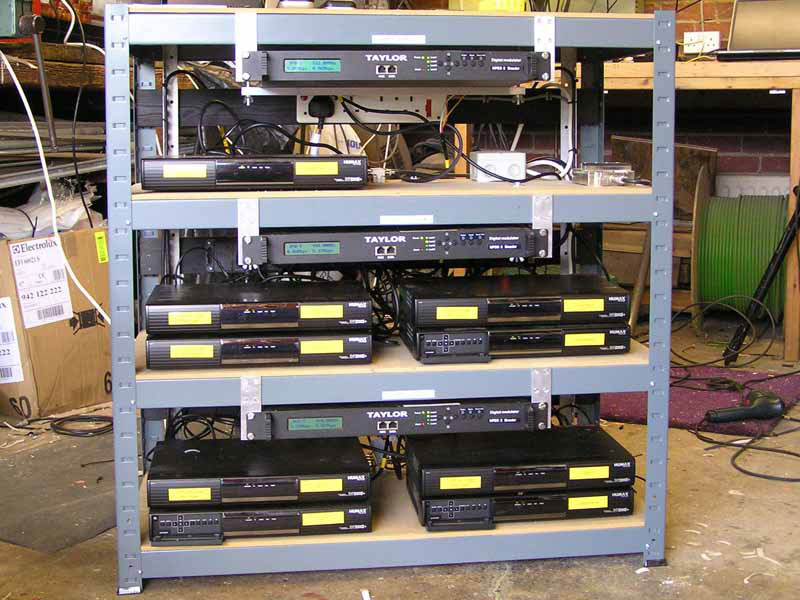
Receivers and DTT modulators on test in the workshop.
CLICK to enlarge image
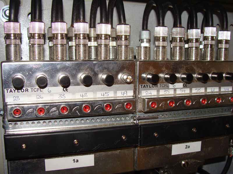
Two sets of cascaded channel filters (there are four blocks of filters if you look closely). This is a cost-effective way of getting a really sharp yet easily adjustable response on each channel. Each signal passes through six passive tuned stages.
CLICK to enlarge image
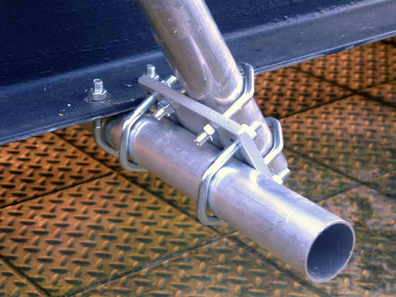
The fixing for a diagonal brace.
CLICK to enlarge image
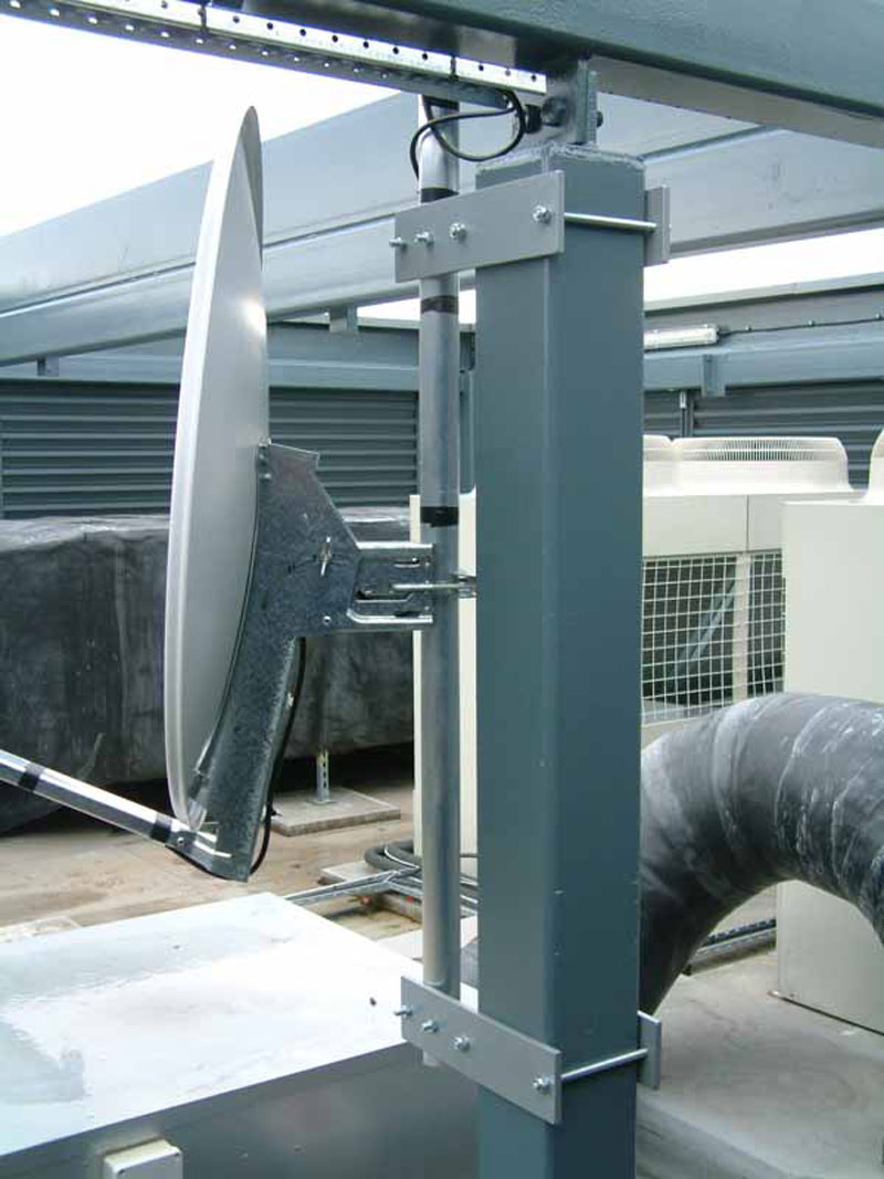
Customised brackets.
CLICK to enlarge image
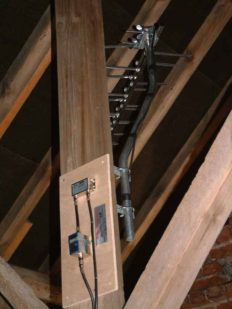
An unusual installation needing a loft aerial, an equalising filter, and a masthead amplifier.
CLICK to enlarge image
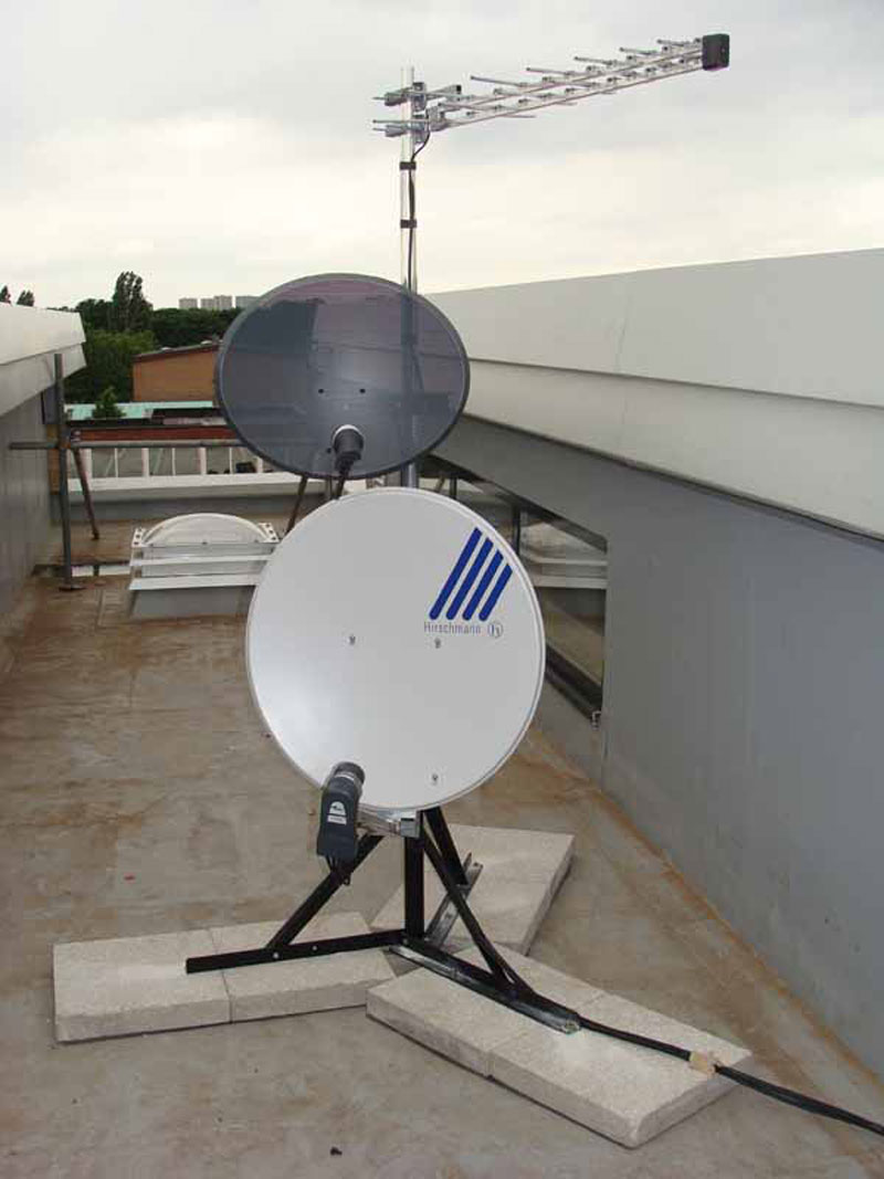
A fairly typical non-penetrating aerial and dish installation.
CLICK to enlarge image

A ‘through the roof’ seal.
CLICK to enlarge image
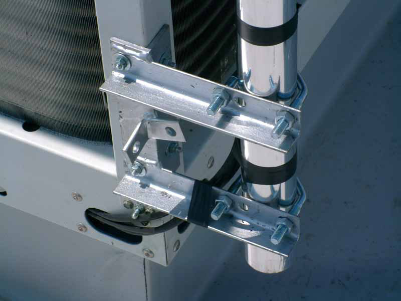
An unusual chimney bracket fixing, one of a pair.
CLICK to enlarge image
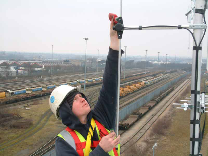
Applying Locktite.
CLICK to enlarge image
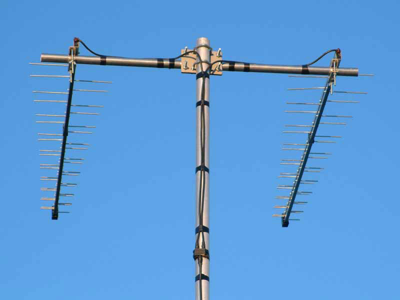
Two log-periodic aerials phased together.
CLICK to enlarge image
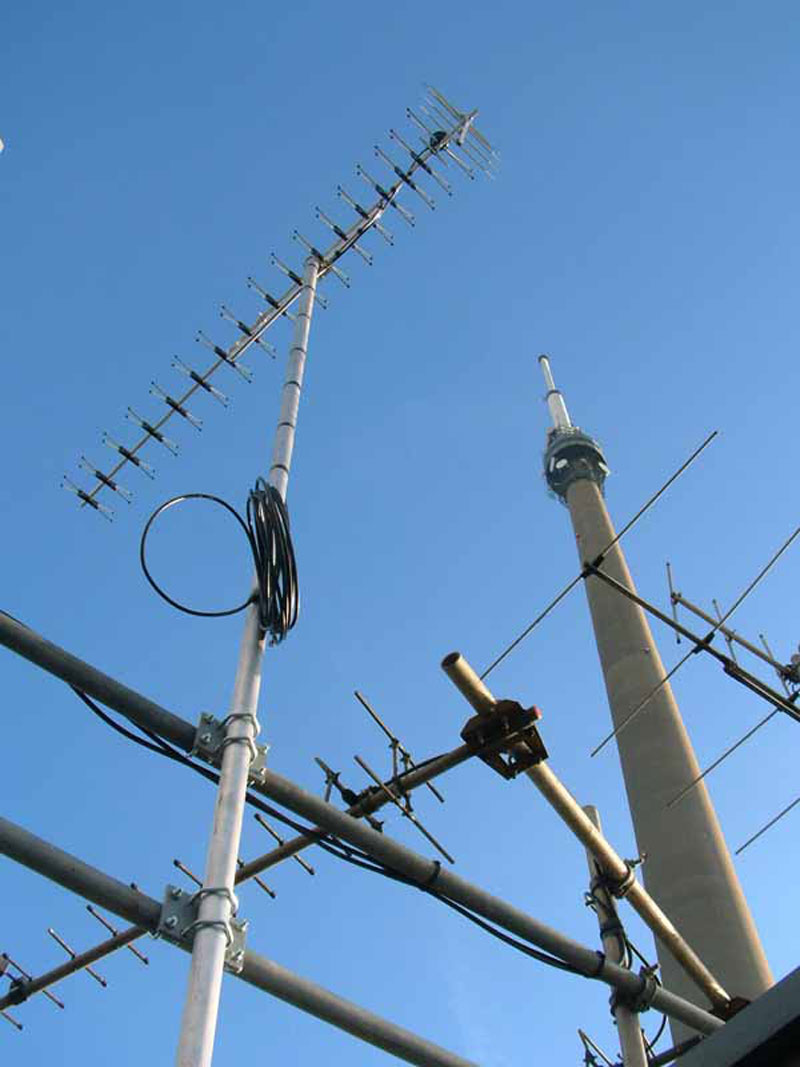
A high gain grouped aerial, an Antiference XG21.
CLICK to enlarge image